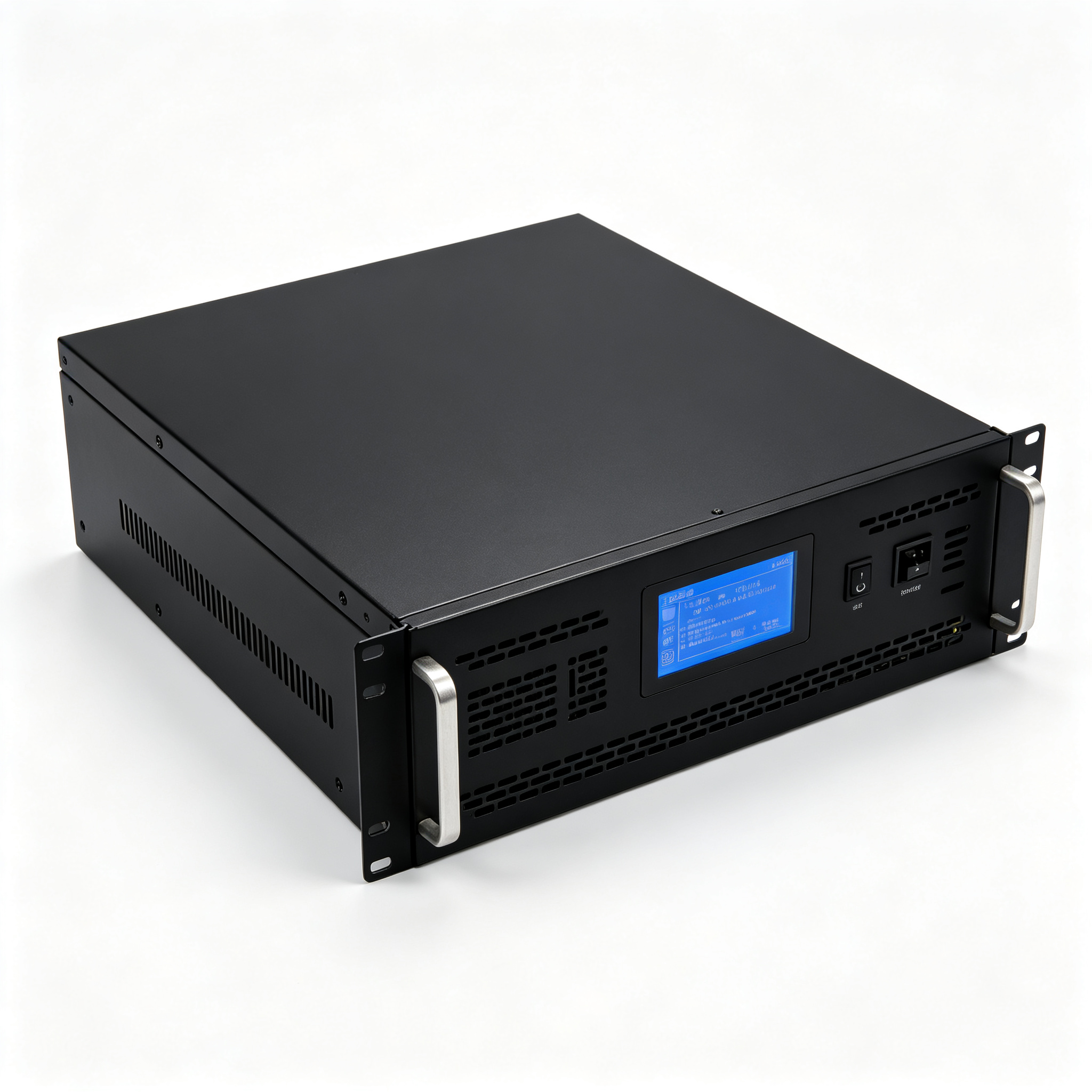
SST
Next-generation power conversion — replacing bulky iron-core transformers with intelligent, bi-directional, high-frequency solid-state devices.
Next-generation power conversion — replacing bulky iron-core transformers with intelligent, bi-directional, high-frequency solid-state devices.
A Solid-State Transformer (SST) uses high-frequency power electronics (SiC MOSFETs, IGBTs) to perform voltage conversion — replacing the traditional copper coils and iron core.
The result: 50-70% smaller footprint, bi-directional energy flow, and full digital control of voltage, current and power quality.
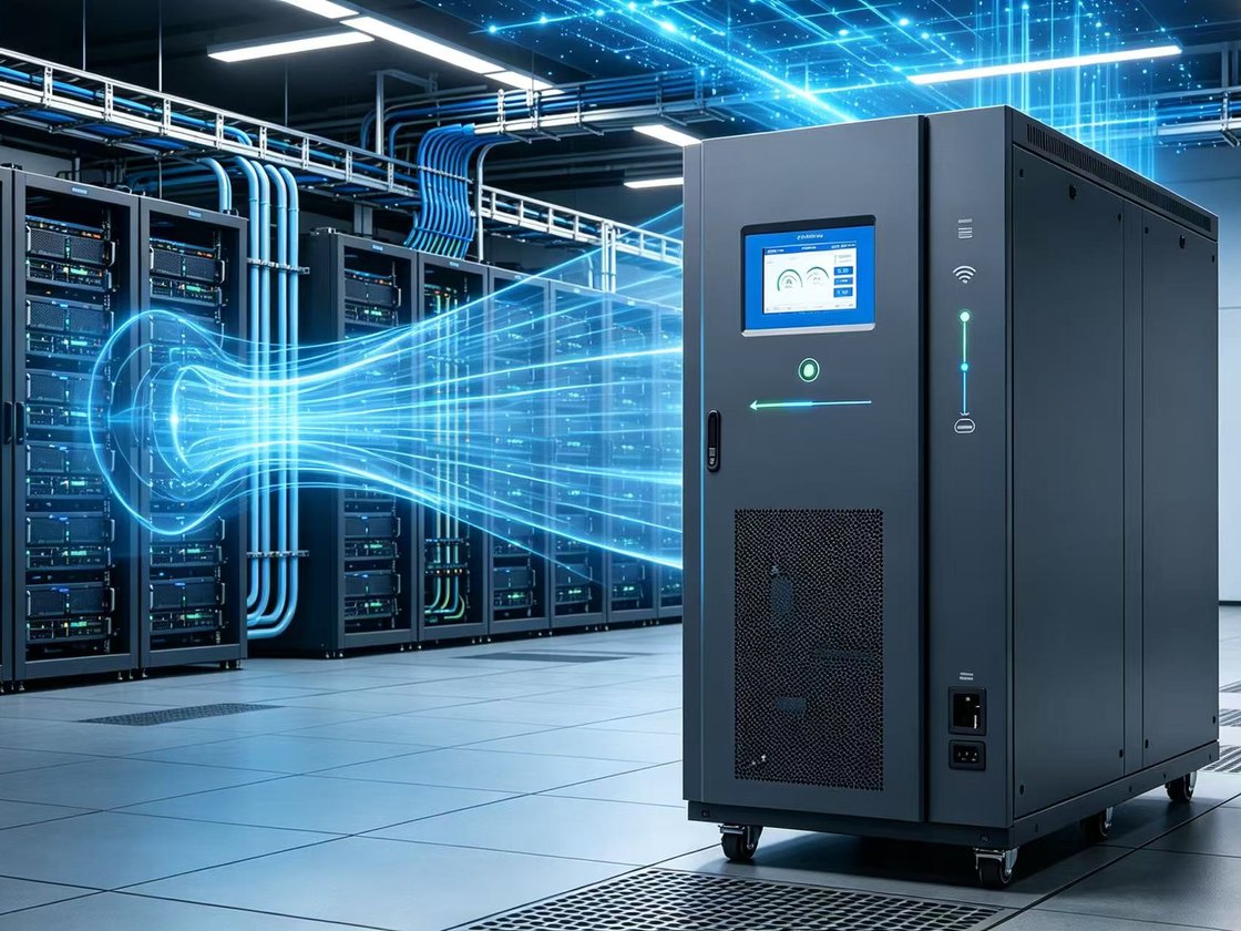
HVDC supply — compact, high-efficiency power delivery for hyperscale computing loads with fewer conversion stages.
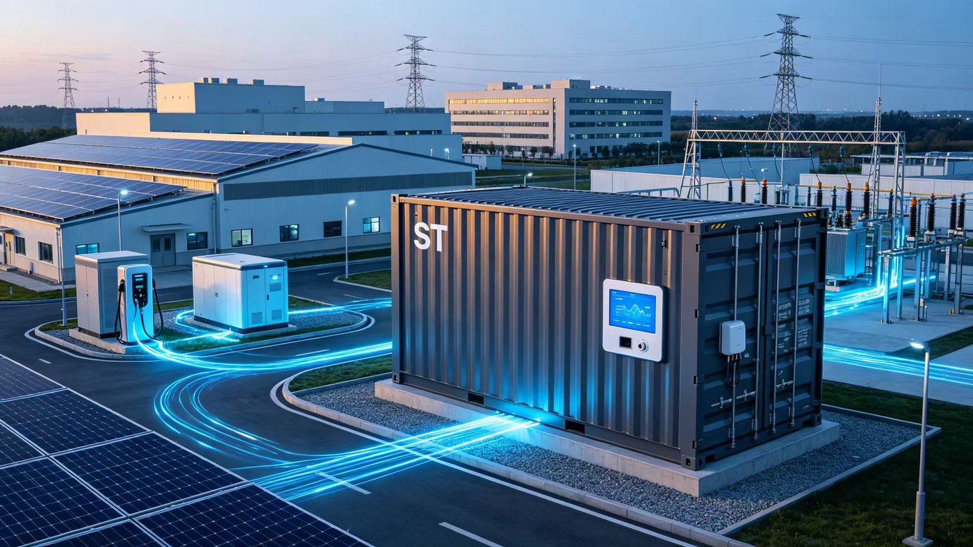
480 kW – 1 MW ultra-fast charging stations; direct MV connection removes the line-frequency transformer and substation room.
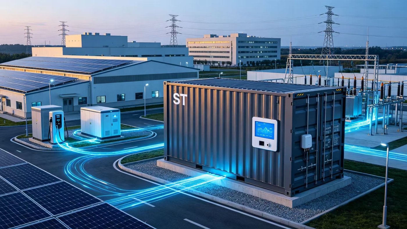
Multi-port interconnection of PV, storage and loads with real-time power quality control and bi-directional dispatch.
Epoxy-potted body with direct copper-bar terminals and class-H insulation. Available as fully potted or coil-potted builds, with natural or forced-air cooling.
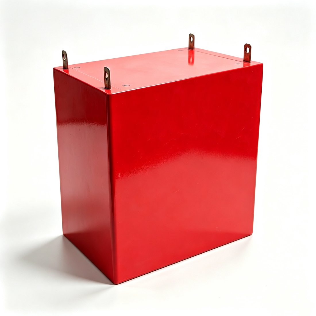
Fully Potted Body
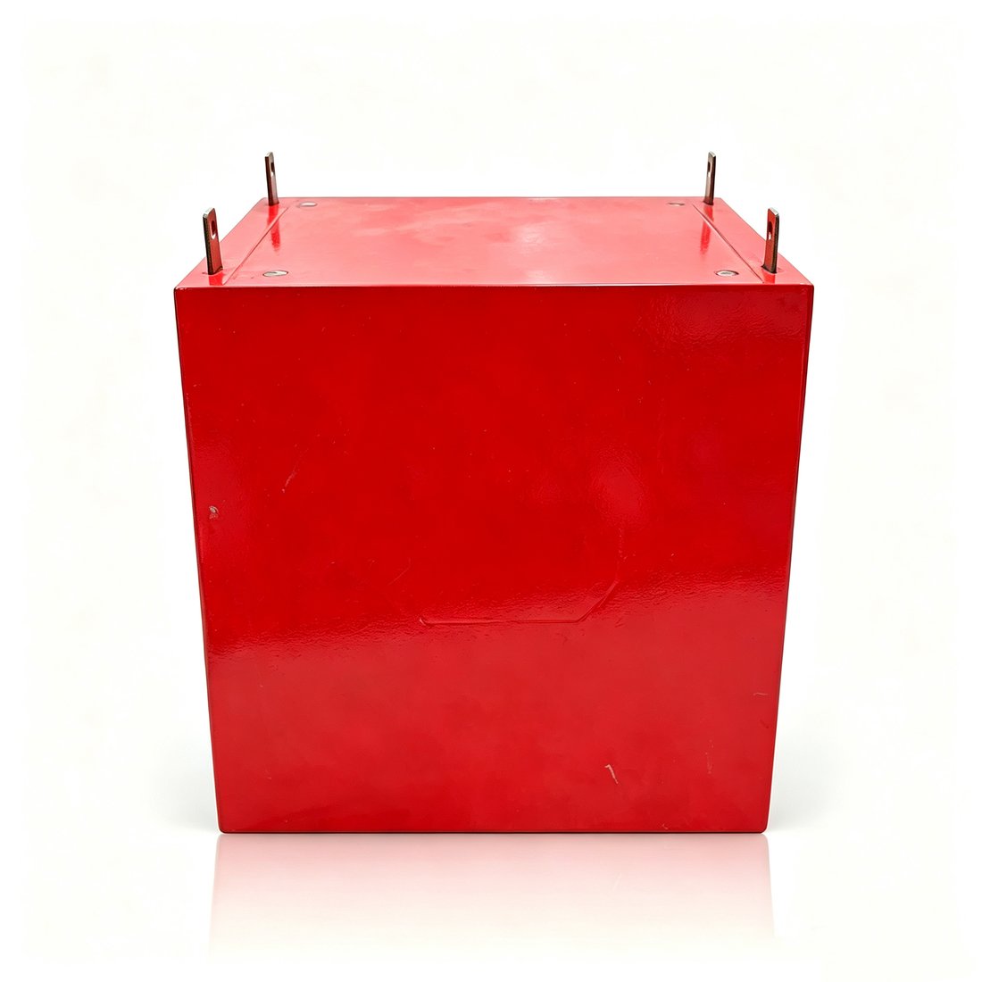
Copper-Bar Terminals
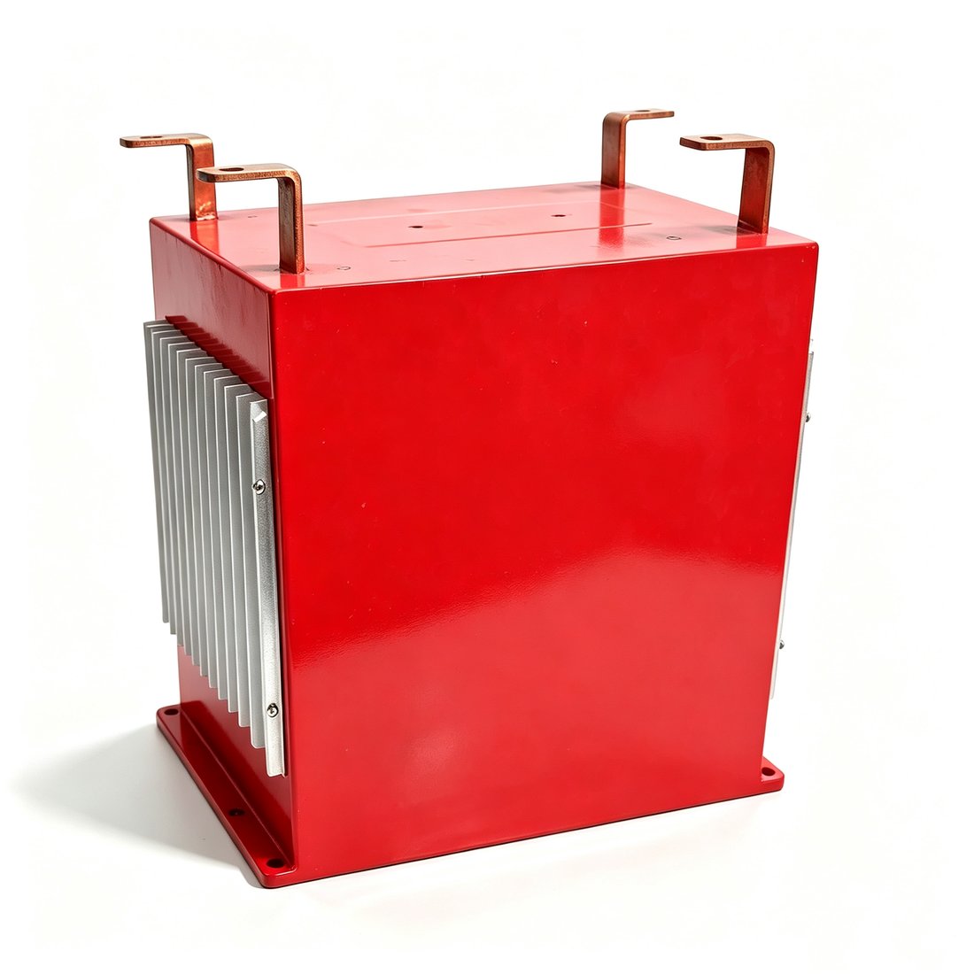
Heatsink Variant
Covers 60 kW – 200 kW, both single- and three-phase designs, all with high-frequency topology and Class H insulation.
| Parameter | 60 kW Single-Phase | 100 kW Single-Phase | 200 kW Three-Phase |
|---|---|---|---|
| Rated Power | 60 kW | 100 kW | 200 kW |
| Phases | Single-phase | Single-phase | Three-phase |
| Operating Frequency | 10 kHz | 10 kHz | 20 kHz |
| Voltage | Primary 3-4: 1000 VDC / Secondary 1-2: 750 VDC, turns ratio 4:3 | Terminals 1-2: 800V / 3-4: 750V | MV side 296.3V / 268.7A; LV side 333.3V / 238.8A |
| Inductance / Leakage | Primary 2 mH ± 10%, Secondary 1.1 mH ± 10%; primary leakage 116 μH, secondary 65 μH | 1-2 inductance 1000 μH, leakage 63 μH (3-4 shorted) | LV winding leakage < 8.6 μH (20 kHz test) |
| Withstand / Insulation | Primary-to-secondary / primary-to-core 35 kVAC / 1 min; secondary-to-core 5 kVAC / 1 min | 1-2 vs 3-4 & core 35 kVAC / 1 min, leakage < 10 mA | MV-to-ground DC35kV / 1min; LV-to-ground DC5kV / 1min; insulation resistance > 100 MΩ @ 1000 VDC |
| Cooling | Natural | Natural | Forced air |
| Insulation Class | Class H | Dry-type | Class H |
| Dimensions | 300×210×370 mm | 360×240×360 mm | ≤ 640×270×530 mm |
Three process series: full-potted (epoxy encapsulation), coil-potted (partial encapsulation) and three-phase integrated designs.
| Model | Rated Power | Insulation | Typical Application |
|---|---|---|---|
| 12 kW - 35 kV | 12 kW | 35 kVAC | Small PET/SST, LV DC distribution |
| 30 kW - 35 kV | 30 kW | 35 kVAC | Small-to-medium power-electronics transformer |
| 45 kW - 35 kV | 45 kW | 35 kVAC | Mid-power DC distribution unit |
| 60 kW - 35 kV | 60 kW | 35 kVAC | Industrial-grade SST |
| 70 kW - 60 kV | 70 kW | 60 kVAC | Medium-high voltage DC distribution |
| 125 kW - 35 kV | 125 kW | 35 kVAC | High-power PET module |
| 150 kW - 35 kV | 150 kW | 35 kVAC | High-power power-electronics transformer |
| Model | Rated Power | Insulation | Typical Application |
|---|---|---|---|
| 30 kW - 35 kV | 30 kW | 35 kVAC | Weight-sensitive mobile equipment |
| 60 kW - 35 kV | 60 kW | 35 kVAC | Well-ventilated cabinet installation |
| Model | Rated Power | Insulation | Typical Application |
|---|---|---|---|
| 150 kW - 35 kV (3-phase) | 150 kW | 35 kVAC | 3-phase high-power PET, PV DC systems |
Share your voltage class, power rating and use case — our power-electronics team will scope a solution.